Page Contents
- 1 OVERVIEW
- 2 SUMMARY OF IMAGES/CLIPS THAT ARE NEEDED
- 3 PANCREAS (TRANSVERSE VIEW)
- 4 THE AORTA (SAGITTAL VIEW)
- 5 THE AORTA (TRANSVERSE VIEW)
- 6 THE IVC (SAGITTAL VIEW)
- 7 THE IVC (TRANSVERSE VIEW)
- 8 LEFT LIVER LOBE (TRANSVERSE VIEW)
- 9 LEFT LIVER LOBE (SAGITTAL VIEW)
- 10 RIGHT LIVER LOBE (TRANSVERSE VIEW)
- 11 RIGHT LIVER LOBE (SAGITTAL VIEW)
- 12 GALLBLADDER ( PATIENT SUPINE)
- 13 GALLBLADDER ( PATIENT LLD)
- 14 COMMON BILE DUCT
- 15 RIGHT KIDNEY (SAGITTAL VIEW)
- 16 RIGHT KIDNEY (TRANSVERSE VIEW)
- 17 LEFT KIDNEY (SAGITTAL & TRANSVERSE VIEWS)
- 18 SPLEEN (SAGITTAL VIEW)
- 19 SPLEEN (TRANSVERSE VIEW)
OVERVIEW
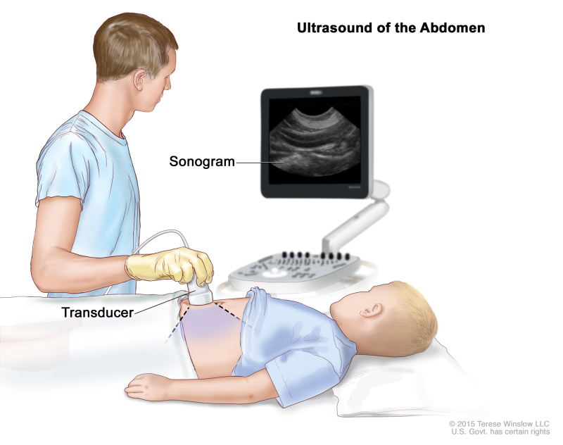
This page covers the important aspects of how to protocol (i.e. conduct) a complete abdominal ultrasound. This is a very commonly conducted study that has a clear protocol in place that will ensure all the proper images are taken. The various components of the study are outlined more below in detail, with example images.
SUMMARY OF IMAGES/CLIPS THAT ARE NEEDED
Pancreas
- Transverse view: image of head, body, and tail if possible. Clip of entire pancreas.
Aorta
- Sagittal view: 2-3 images showing length of aorta from liver to bifurcation. Often times proximal, mid, and distal images are taken.
- Transverse view: image showing mid-abodminla aorta and bifurcation of aorta. Clip of aorta bifurcating into the common illiacs.
Inferior Vena Cava (IVC)
- Sagittal view: one image of inter hepatic vessel, one image of entire length inferior to liver.
- Transverse view: image showing the entering of hepatic veins to the
Left Lobe Liver
- Sagittal view: medial, mid, and lateral sections of liver lobe. Clip of entire liver lobe.
- Transverse view: superior, mid, and inferior sections of liver lobe. Clip of entire liver lobe.
Right Lobe Liver
- Sagittal view: medial, mid, and lateral sections of liver lobe. Clip of entire liver lobe.
- Transverse view: superior, mid, and inferior sections of liver lobe. Clip of entire liver lobe.
Gallbladder
- Long axis view: still image showing this axis. Clip of entire organ in this axis.
- Short axis view: still image showing this axis. Clip of entire organ in this axis.
Common Bile Duct
- Still image showing common bile duct and portal vein
Right Kidney
- Sagittal view: long axis of organ measured with calipers. Clip showing entire long axis of kidney.
- Transverse view: images of upper pole, mid pole, and lower pole. Clip showing entire kidney through this view.
Left Kidney
- Sagittal view: long axis of organ measured with calipers. Clip showing entire long axis of kidney.
- Transverse view: images of upper pole, mid pole, and lower pole. Clip showing entire kidney through this view.
Spleen
- Sagittal view: long axis of organ measured with calipers and clip of as much of organ as possible.
- Transverse view: still image in this view, and clip showing as much of organ as possible.
PANCREAS (TRANSVERSE VIEW)
The first organ to begin with for this exam is the pancreas. This is because the pancreas can easily become “gassed” out during later parts of the exam. All images of this organ will be acquired in the transverse orientation. The goal is to acquire still images of the head, body, and tail (if possible) for this organ, as well as a clip that scans through its entirely.
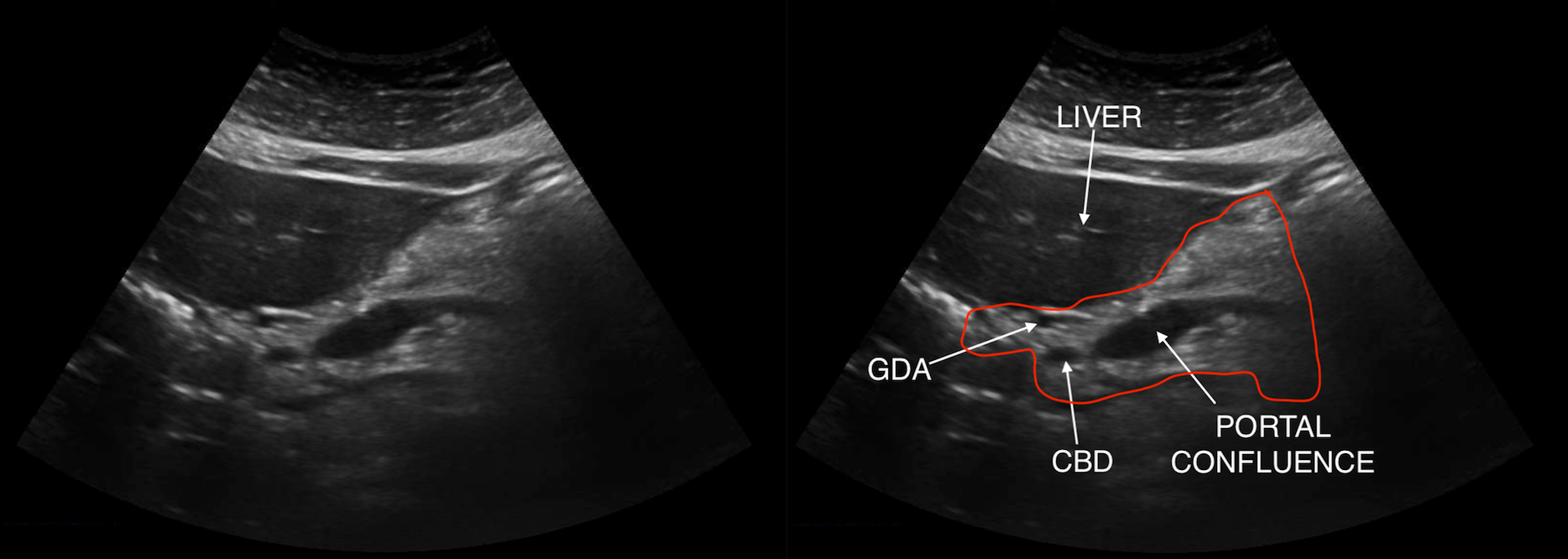
HEAD OF THE PANCREAS
For the head of the pancreas, it is useful to try and find the gastro-duodenal artery (GDA) and the common bile duct (CBD) in the transverse image (which serve as landmarks for the head of the pancreas). A still image of the head of the pancreas should be taken (such as the example shown below) that demonstrates the important landmarks needed to identify it as the true head of the pancreas.
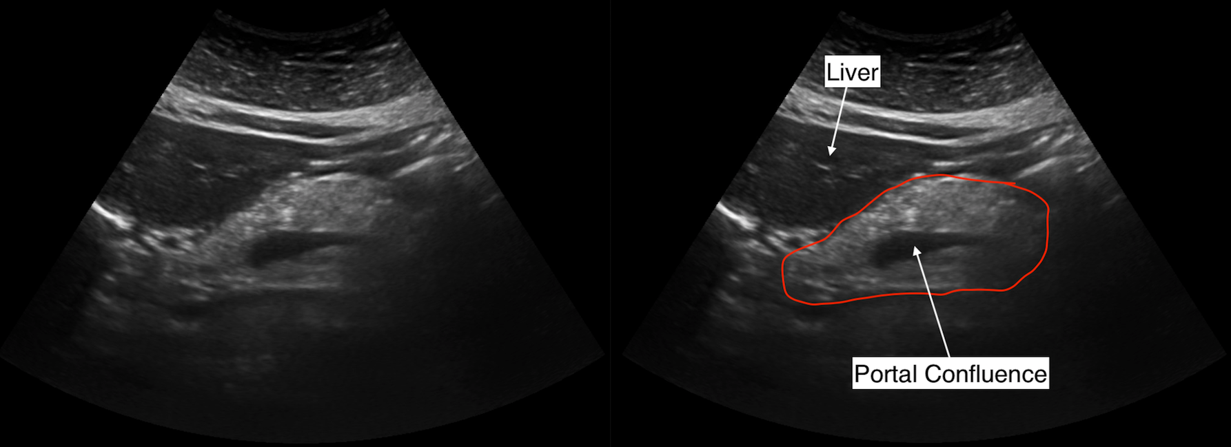
BODY OF THE PANCREAS
The body of the pancreas can be found by following the head of the pancreas more towards the left side of the patient. The portal confluence can still be appreciated when a still image is taken of the body of the pancreas (which is shown in the image below).
TAIL OF THE PANCREAS
The tail of the pancreas can sometimes by challenging to find, and a still image can not always be acquired easily.
CLIP OF THE ENTIRE PANCREAS
After taking the above still images have been saved, a clip should be acquired that shows as much of the pancreas as possible. An example is seen below:
THE AORTA (SAGITTAL VIEW)
Next the aorta will be imaged in the sagittal plane. The goal will be to acquire still images that show the entire length of the aorta from the liver down to the bifurcation. Generally 2-3 images will be needed to do this.
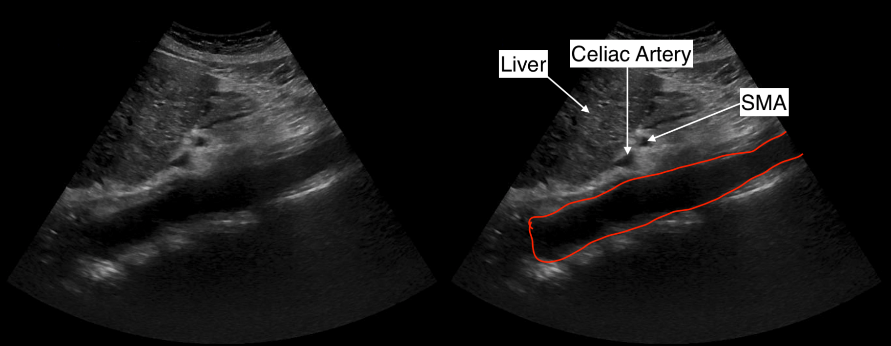
PROXIMAL AORTA
The proximal aorta can be seen running alongside the liver. In some cases the celiac artery and the superior mesenteric artery (SMA) can be seen nearby/coming off of it. The image below shows an example of this image that should be aquired.
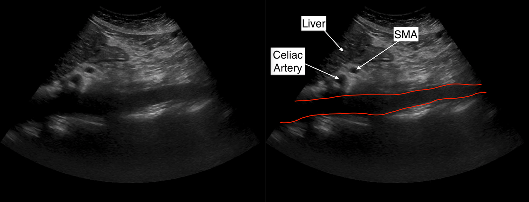
MID AORTA
The mid aorta can be seen lower on the abdomen. In some cases the celiac artery and the superior mesenteric artery (SMA) can be seen nearby/coming off of it. The image below shows an example of this image that should be aquired.
DISTAL AORTA
The distal aorta can be seen lower on the abdomen. The purpose of this image is to try and image the aorta right as it bifurcates into the common iliac arteries. It is important to note that sometimes showing the iliac arteries and the aurora in the same plane/still image can be challenging. An example of this image is shown below.

THE AORTA (TRANSVERSE VIEW)
Next the aorta will be imaged in the transverse plane. The goal will be to acquire a still image that shows the mid-abodminal aorta, and a clip of the bifurcation of the aorta into the common iliac arteries.
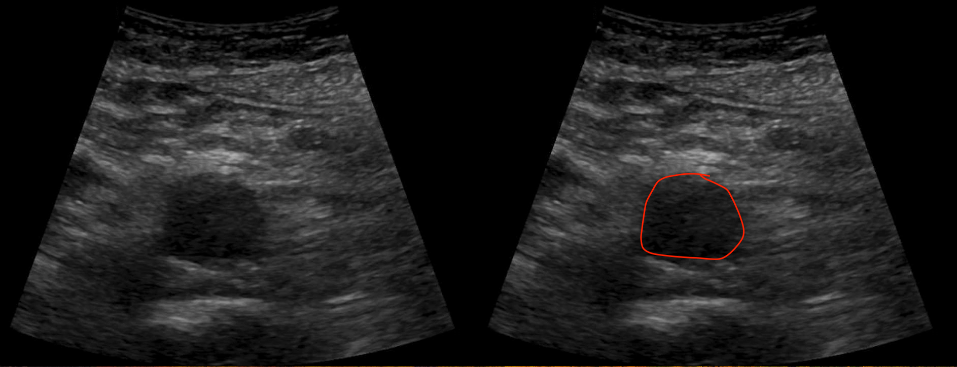
MID-ABDOMINAL AORTA
A still image of the abdominal aorta can be acquired and saved. An example is shown below.
BIFURCATION OF AORTA
A clip is also taken that shows the bifurcation of the aorta into the common iliac arteries. An example is shown below.

THE IVC (SAGITTAL VIEW)
The next thing to image will be the IVC in the sagittal plane. The goal here is to try and show the entire length of the structure starting from the inter hepatic portion of the vessel. This is commonly done by taking two still images, one of the inter-hepatic portion of the IVC and one showing as much of the entire length inferior to the liver.
INTER-HEPATIC PORTION OF IVC
By scanning the right lobe of the liver, it should be possible to locate the portion of the IVC that courses through the liver. This image should be saved to show that there is no thrombus in this portion of the vessel. An example of this image is shown below.
ENTIRE LENGTH OF IVC
By traveling more inferiorly, the entire length of the IVC should try to be captured on a still image. The the image below shows an example of this.
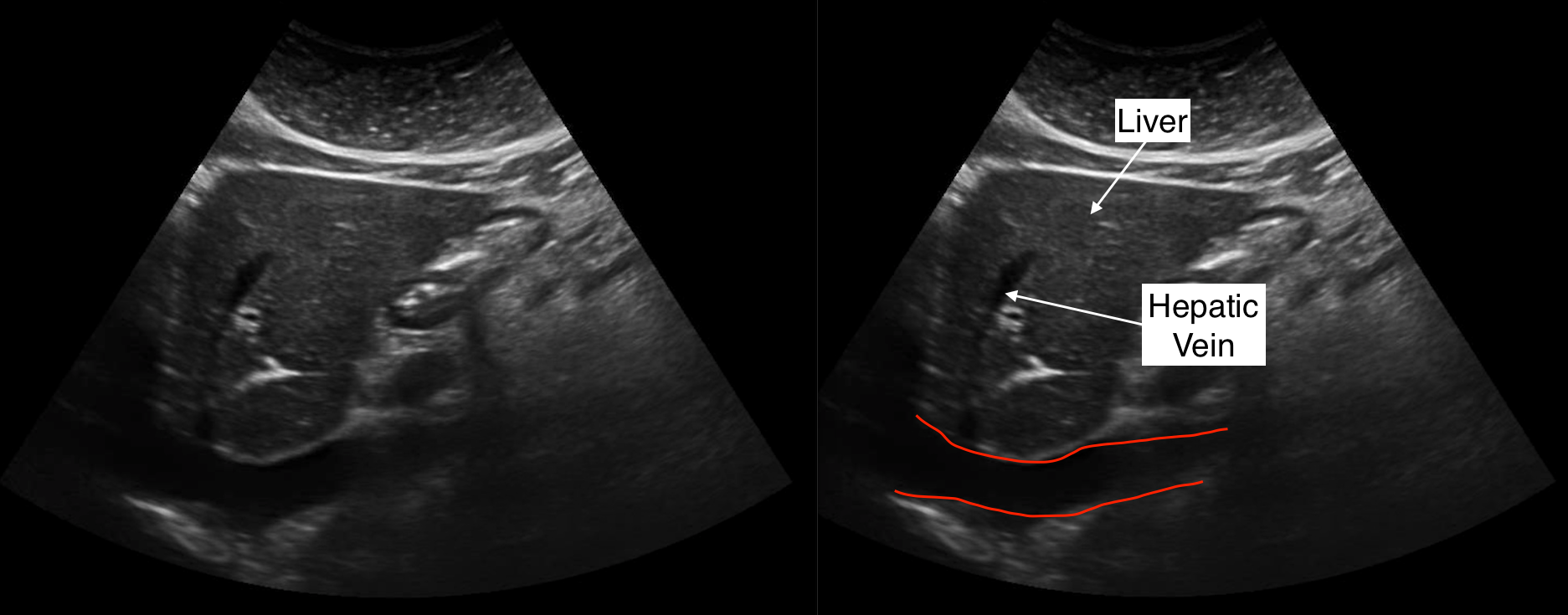
THE IVC (TRANSVERSE VIEW)
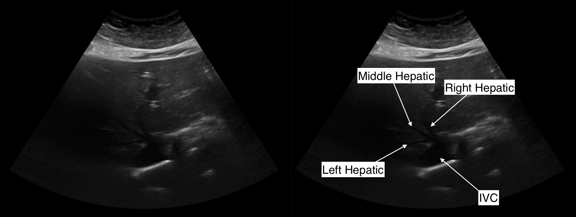
The IVC can also be appreciated in the transverse view. Only one image is needed from this view, one that shows the liver at the level of where the hepatic veins connect to the IVC (as shown in the example below).
LEFT LIVER LOBE (TRANSVERSE VIEW)
The next organ to focus on will be the liver. It becomes more manageable to scan the liver when it is split into lobes. The first lobe to image will be the left liver lobe in the transverse orientation. The goal of these scans is to capture still images that demonstrate the appearance leftmost, middle, and rightmost sections of the left liver lobe, and to also provide a video clip scanning through the entire left liver lobe.
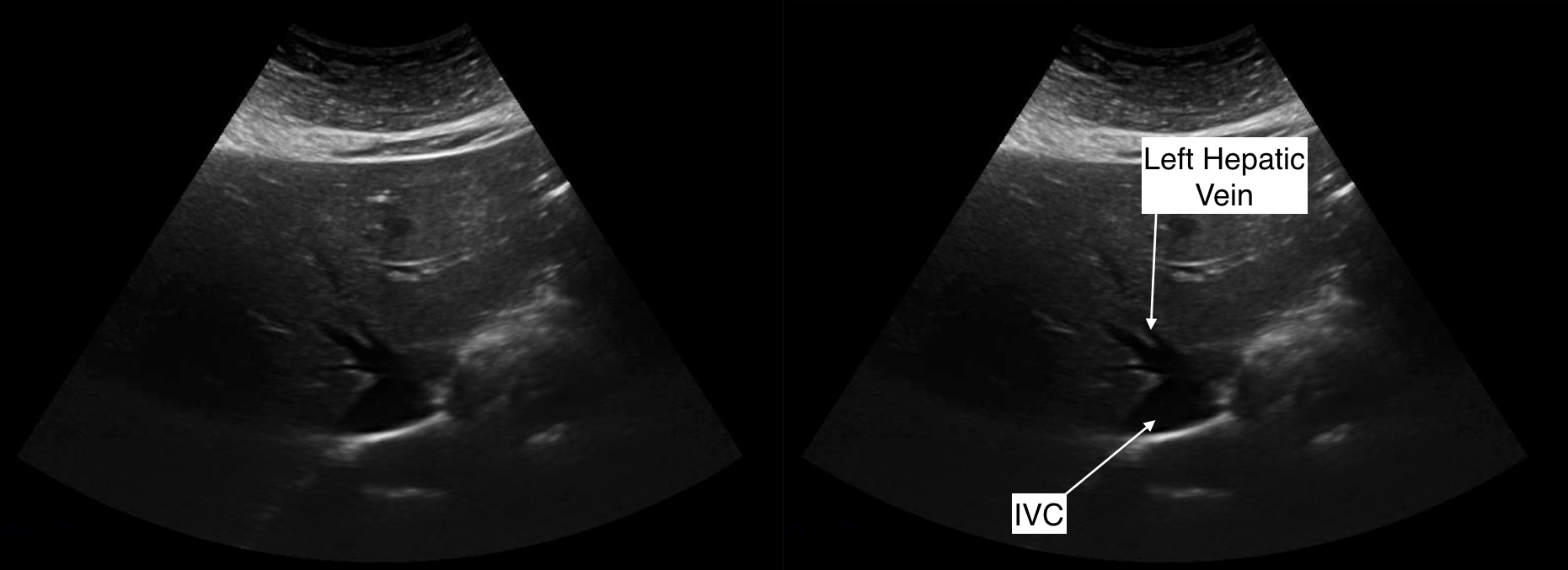
SUPERIOR PORTION OF LEFT LIVER LOBE
A superior section of the left liver lobe should be imaged at the level of the left hepatic vein. An example of this is shown below.
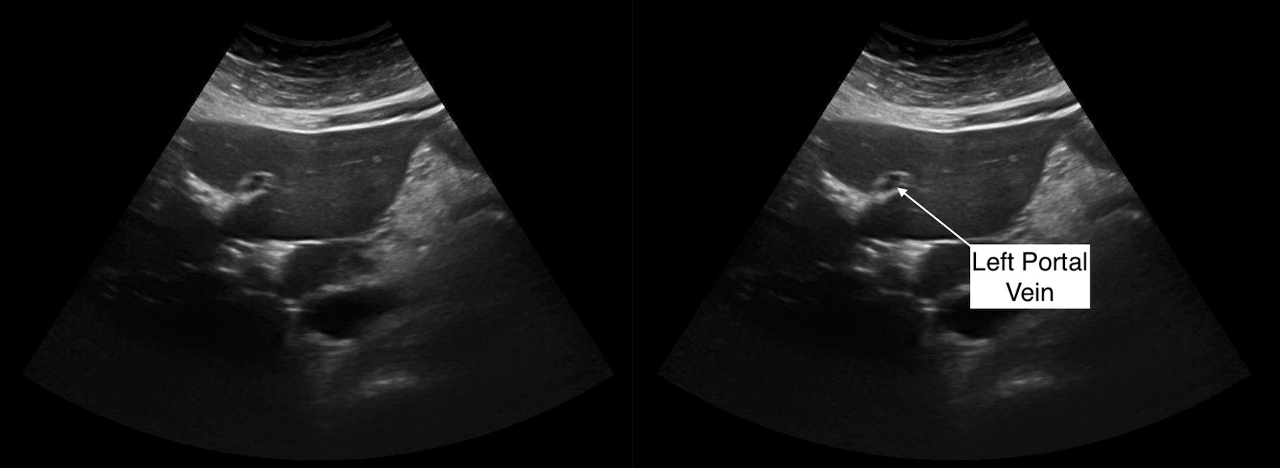
MIDDLE PORTION OF LEFT LIVER LOBE
By scanning lower on the left lobe of the liver, the left portal vein can be visualized and a still image can be taken at this level to document the appearance of the middle portion fo the left liver lobe. An example is shown below.
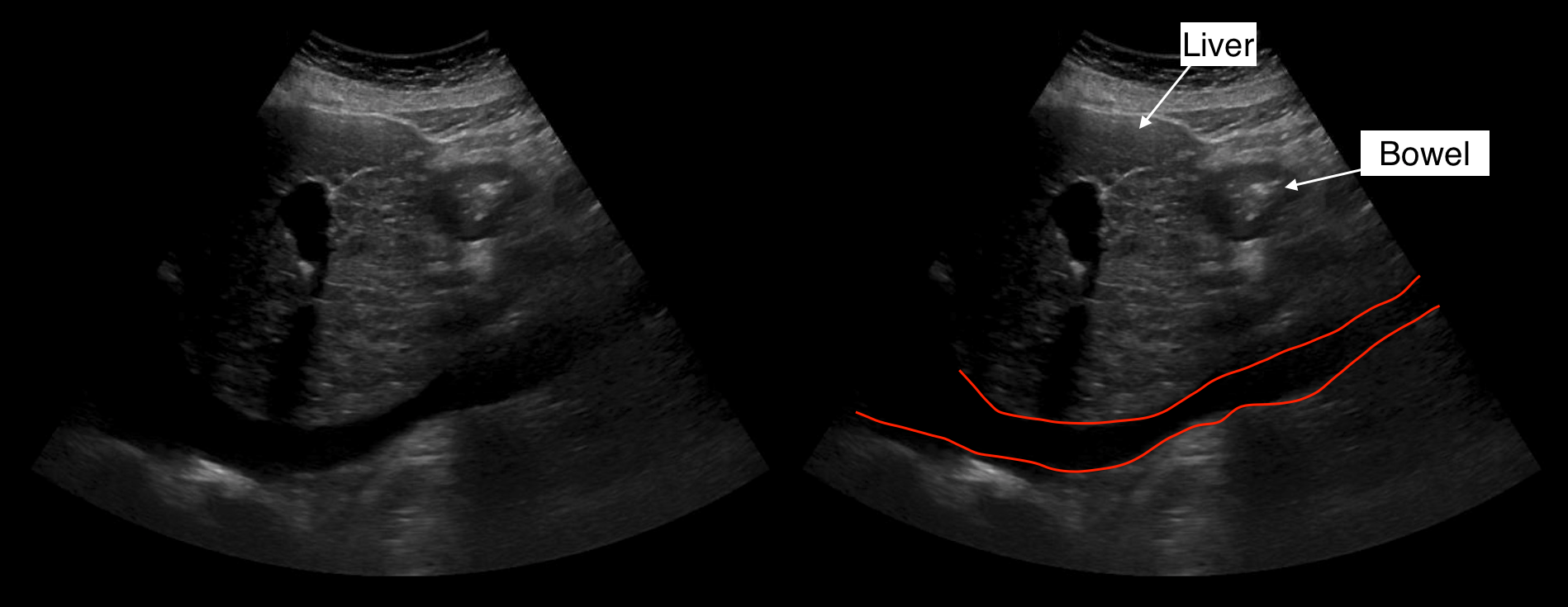
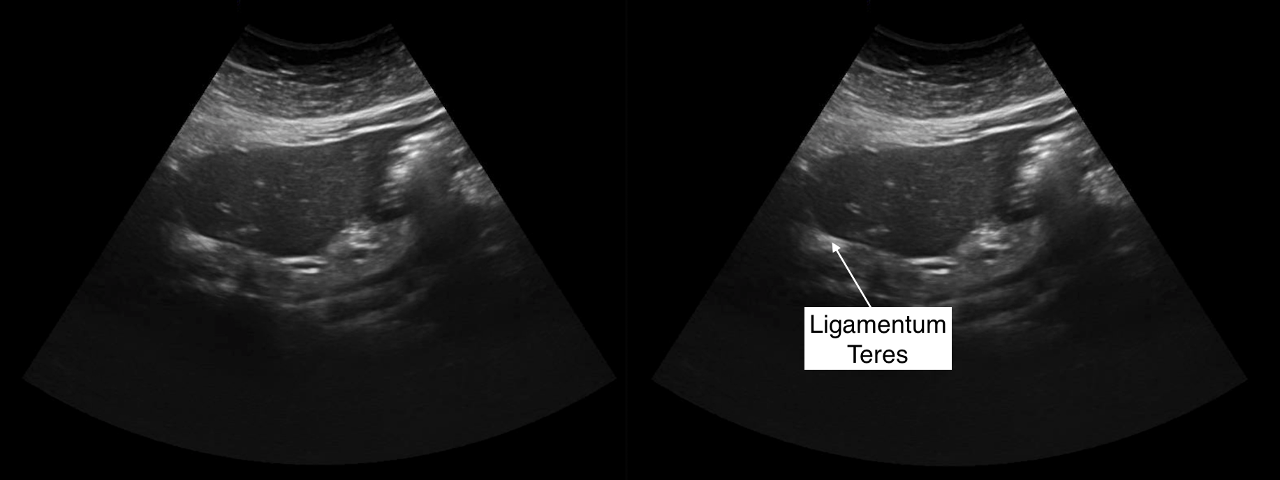
INFERIOR PORTION OF LEFT LIVER LOBE
Scanning even further towards the inferior aspect of this lobe, the ligamentum trees should be visualized, and a still image can be taken at this level to document the appearance of the inferior portion fo the left liver lobe. An example is shown below.
CLIP OF LEFT LIVER LOBE
After the still images have been taken, a clip of the entire left liver lobe can be taken. An example is shown below.
LEFT LIVER LOBE (SAGITTAL VIEW)
The next thing to scan will be the left liver lobe in the sagittal orientation. The goal of these scans is to capture still images that demonstrate the appearance of the medial, middle, and lateral sections of the left liver lobe, and to also provide a video clip scanning through the entire left liver lobe.
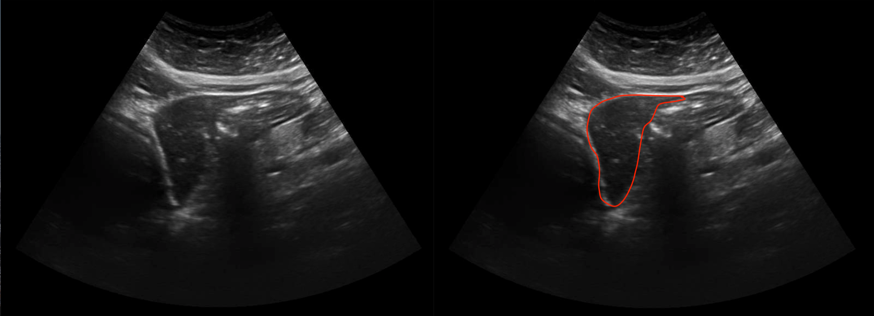
MEDIAL PORTION OF LEFT LIVER LOBE
Scanning from the medial aspect of the liver, the leftmost portion of the left liver lobe can be appreciated. This will only include a small cross section of the liver, as seen in the example below.
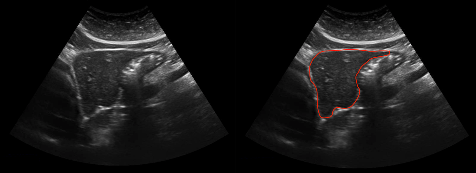
MIDDLE PORTION OF LEFT LIVER LOBE
By then scanning more laterally, the middle portion of the left liver lobe can be imaged as well. This will be a larger cross section compared to the lateral portion (as seen in the image below).
LATERAL PORTION OF LEFT LIVER LOBE
By then scanning even more laterally, the lateral portion of the left liver lobe can be imaged as well. This will be a larger cross section compared to the lateral portion (as seen in the image below).
CLIP OF LEFT LIVER LOBE
After the still images have been taken, a clip of the entire left liver lobe can be taken. The An example is shown below.
RIGHT LIVER LOBE (TRANSVERSE VIEW)
The next organ to focus on will be the liver. It becomes more manageable to scan the liver when it is split into lobes. The second lobe to image will be the right liver lobe in the transverse orientation. The goal of these scans is to capture still images that demonstrate the appearance of the superior, middle, and inferior sections of the right liver lobe, and to also provide a video clip scanning through the entire right liver lobe.
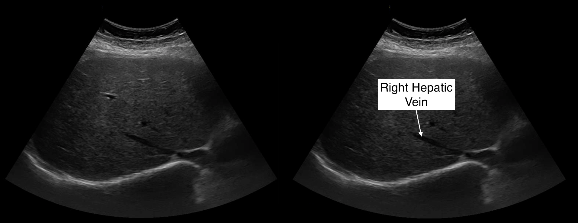
SUPERIOR PORTION OF RIGHT LIVER LOBE
The superior section of the right liver lobe should be imaged at the level of the left hepatic vein. An example of this is shown below.
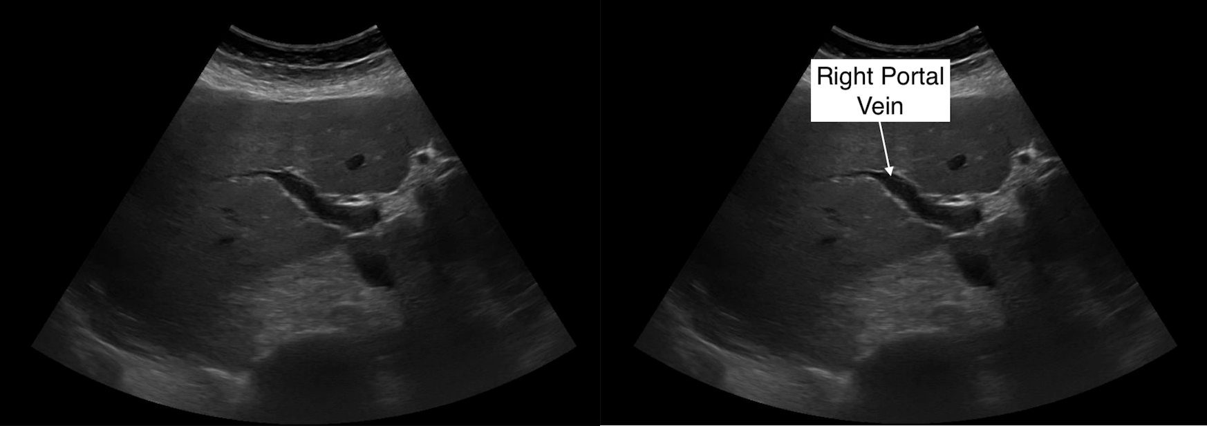
MIDDLE PORTION OF RIGHT LIVER LOBE
By scanning slightly lower on the patient the middle portion of the right liver lobe can be imaged. This image should be at the level of the portal vein (as shown in the example below).
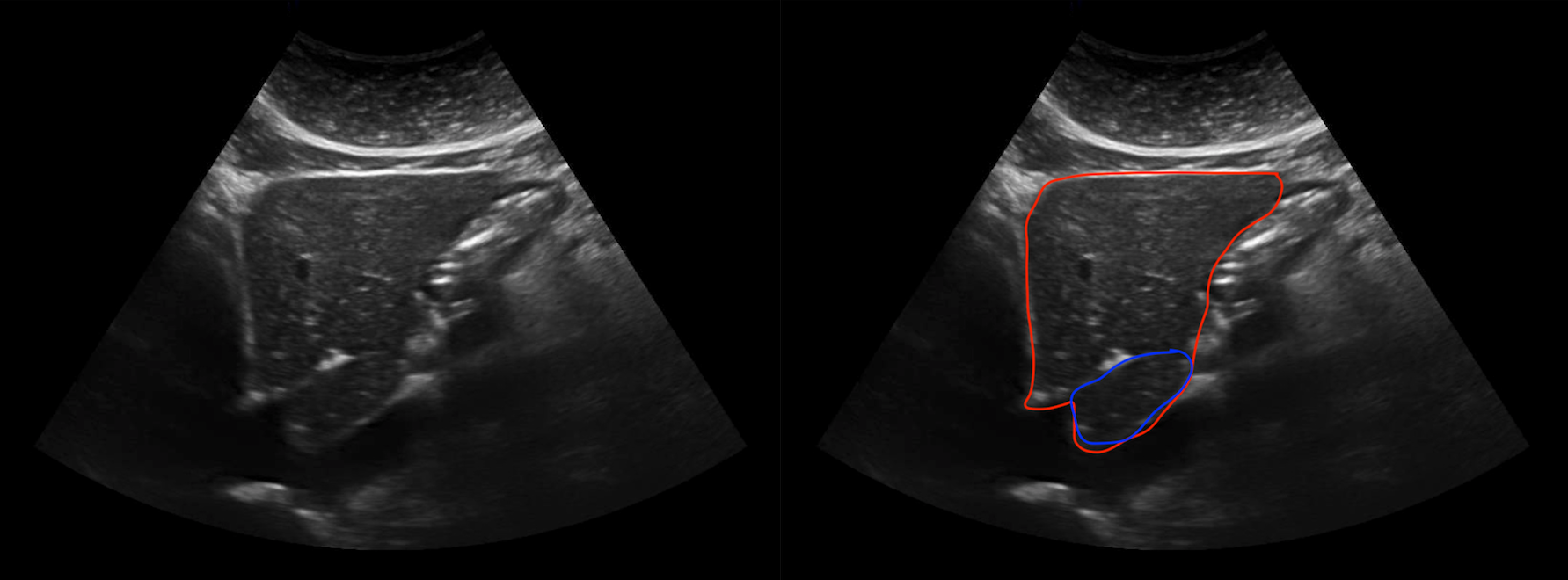
INFERIOR PORTION OF RIGHT LIVER LOBE
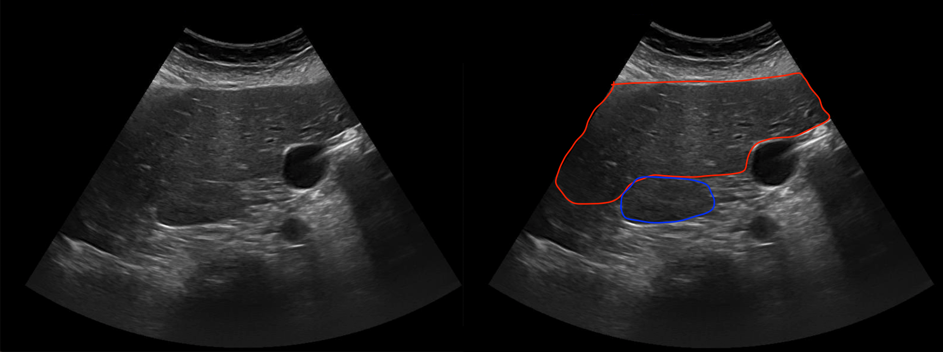
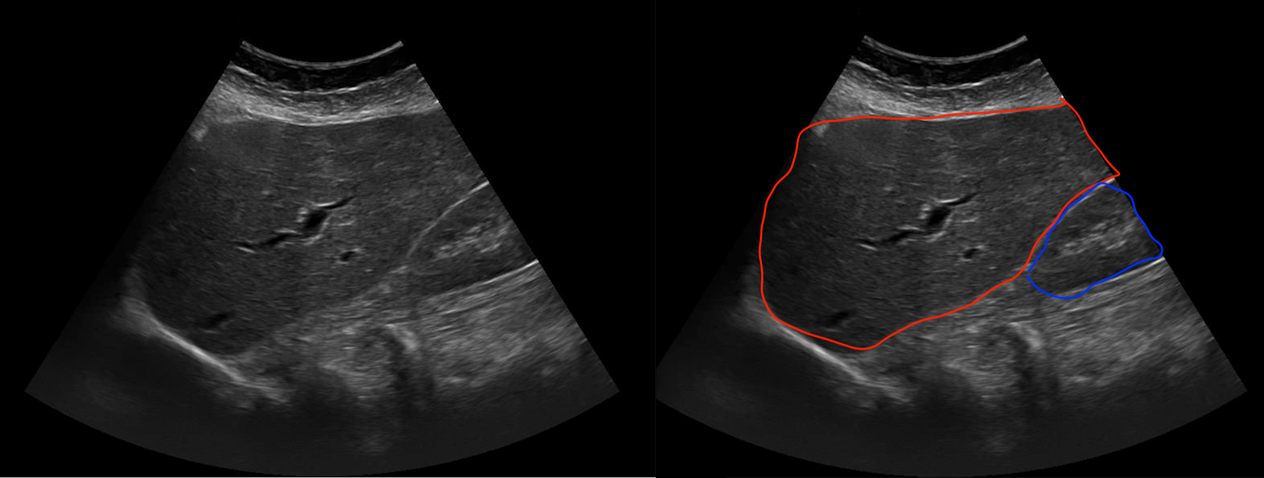
By scanning even lower, the inferior aspect of the right liver lobe can be imaged. This image should include a portion of the right kidney. An example is shown below.
CLIP OF RIGHT LIVER LOBE
After the still images have been taken, a clip of the entire right liver lobe can be taken. This is the larger lobe of the liver, and may require multiple clips to be taken to transverse it (as seen below).
RIGHT LIVER LOBE (SAGITTAL VIEW)
The next thing to scan will be the right liver lobe in the sagittal orientation. The goal of these scans is to capture still images that demonstrate the appearance of the medial, middle, lateral inferior sections of the right liver lobe, and to also provide a video clip scanning through the entire right liver lobe.
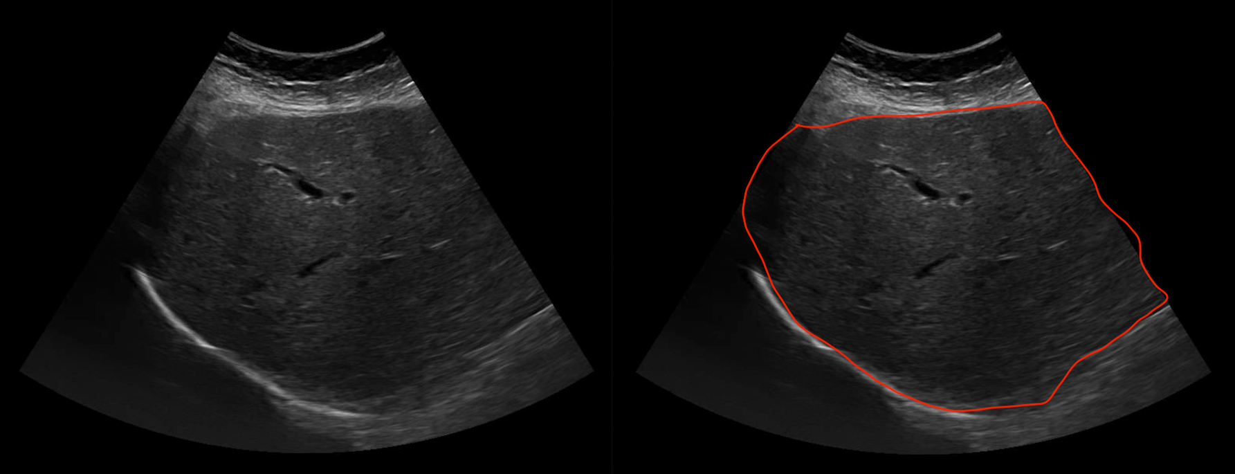
MEDIAL PORTION OF RIGHT LIVER LOBE
Scanning from the medial aspect of the liver, the medial portion of the left liver lobe can be appreciated. An example is shown below.
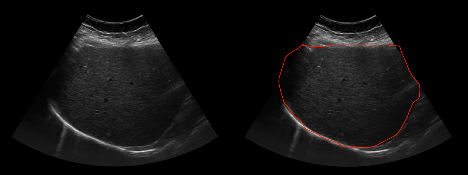
MIDDLE PORTION OF RIGHT LIVER LOBE
By scanning more laterally, the middle portion of the right liver lobe can be imaged. An example is shown below.
LATERAL PORTION OF RIGHT LIVER LOBE
By scanning even more laterally, the lateral portion of the right liver lobe can be imaged. An example is shown below.
CLIP OF RIGHT LIVER LOBE
After the still images have been taken, a clip of the entire right liver lobe can be taken. An example is shown below.
GALLBLADDER ( PATIENT SUPINE)
The next organ to focus on will be the gallbladder. The gallbladder is imaged both when the patient is supine and in the left lateral decubitus (LLD) position. The goal will be to start with the patient supine and then take an image of the long axis (often sagittal) of the gall bladder, as well as a clip of it. Then the same will be done for the short axis of the gall bladder (often transverse) where a still image and clip is collected.
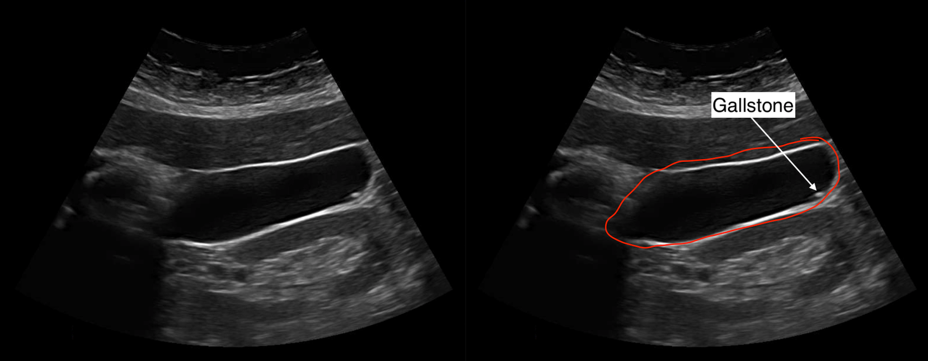
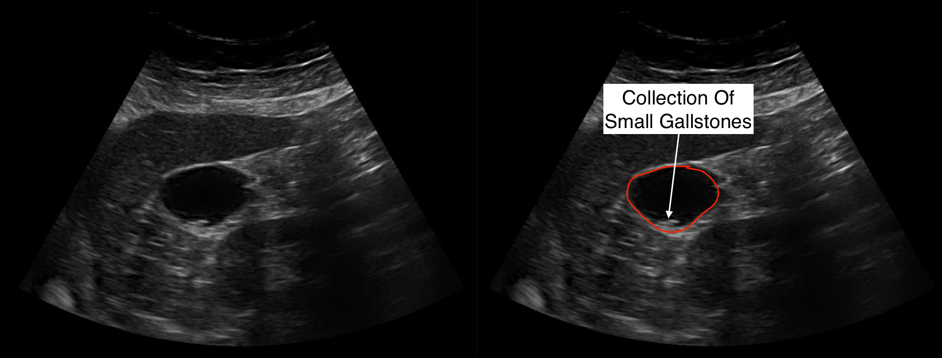
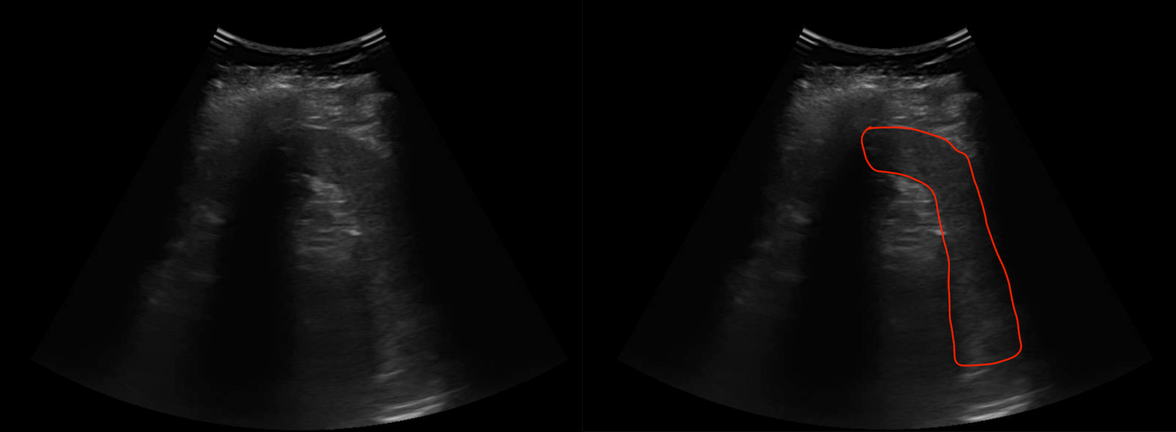
LONG AXIS OF THE GALLBLADDER
The gall bladder can be found inferior to the liver. A still image of the long axis of this organ should be taken similar to the example below.
CLIP OF ENTIRE GALLBLADDER IN LONG AXIS
After the still image is saved, a clip scanning through the entire long axis of the gallbladder can be taken as shown in the example below.
SHORT AXIS OF THE GALLBLADDER
The short axis of the gallbladder should also be imaged as seen in the example below.
CLIP OF ENTIRE GALLBLADDER IN SHORT AXIS
After the still image is saved, a clip scanning through the entire short axis of the gallbladder can be taken as shown in the example below.
GALLBLADDER ( PATIENT LLD)
After images of the gallbladder are taken in the supine position, the same exact set of images/clips will be taken with the patient in the LLD position: still images of the organ in its long axis and short axis, and then corresponding clips as well. Examples for all of these images are omitted here (because they will be very similar to those shown in the previous section).
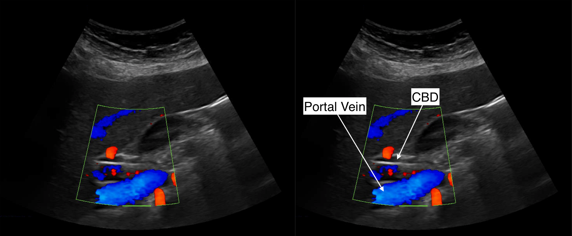
COMMON BILE DUCT
The next structure to image is the common bile duct (CBD). The exact orientation of the probe (sagittal, transverse, somewhere in between) may vary patient to patient. The common bile duct can be found above the portal vein, and can be more easily identified with the addition of color flow (as it is avascular/colorless and the portal vein is vascular/colorful). An example showing this is found below.
RIGHT KIDNEY (SAGITTAL VIEW)
The next organ to focus on will be the right kidney in the sagittal plane. The goal will be to measure the kidney with calipers on its long axis, and to take a clip of the entire kidney in this plane.
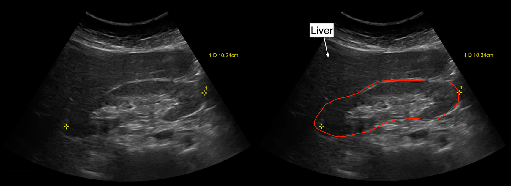
LONG AXIS OF KIDNEY
The long axis of the kidney can be measured in the sagittal plane with calipers. An example of this is shown below.
CLIP OF LONG AXIS OF KIDNEY
After the still image is taken, a clip of the entire long axis of the kidney can be taken (as shown in the example below).
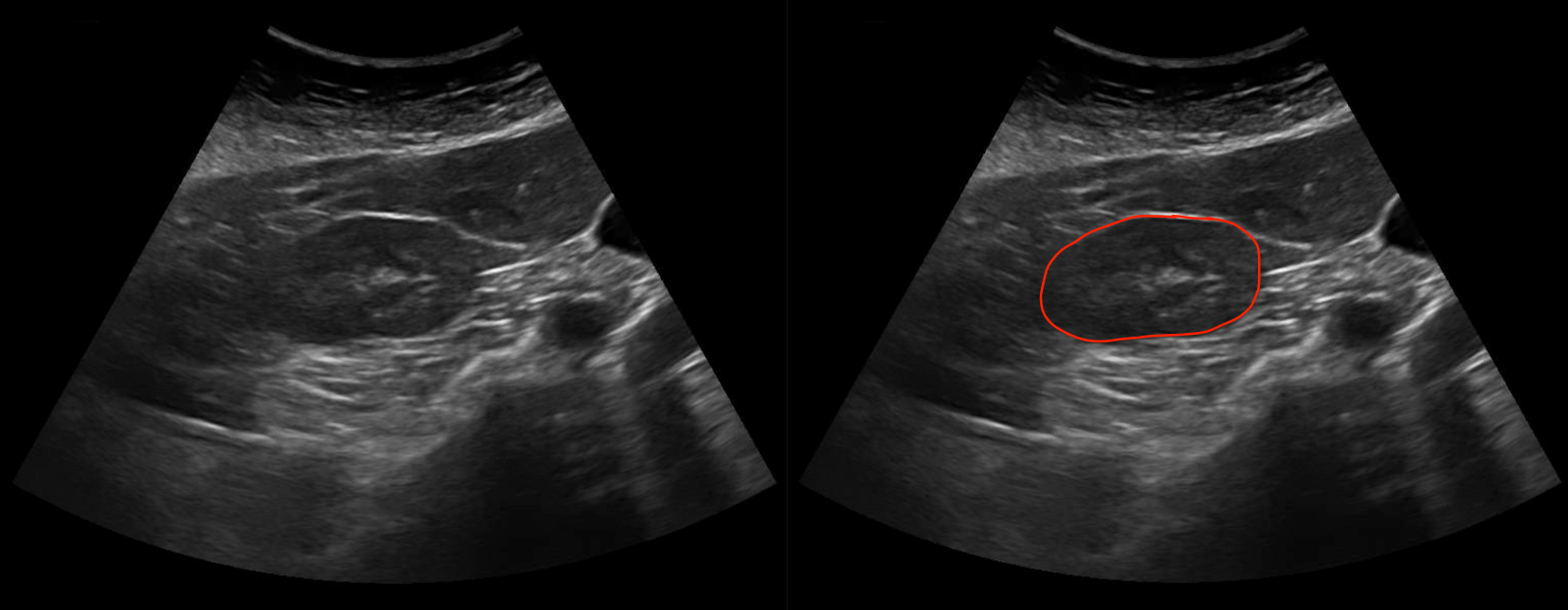
RIGHT KIDNEY (TRANSVERSE VIEW)
The right kidney can now be imaged in the transverse orientation. The goal will be to take still images of the upper pole, the mid pole, and the lower pole, as well as a clip that scans through the entire organ in this transverse orientation.
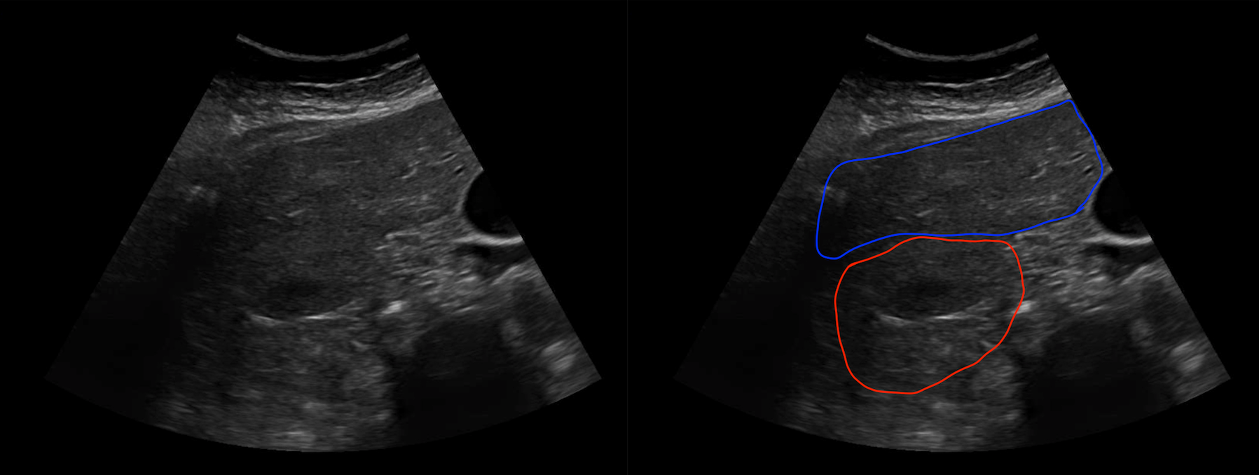
UPPER POLE OF KIDNEY
The upper pole of the kidney is located next to the liver parenchyma, as seen in the example below.
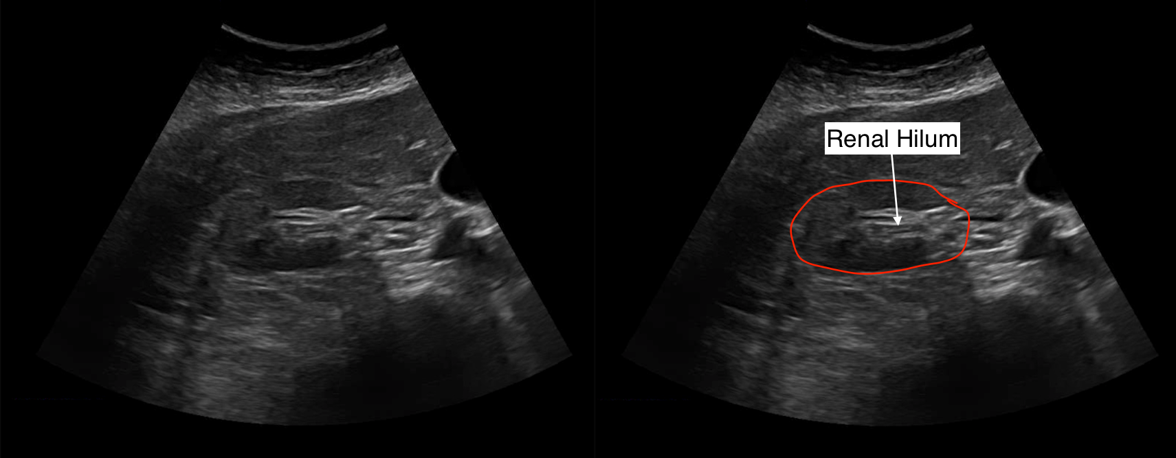
MID POLE OF KIDNEY
The mid pole of the kidney is located lower, and sometimes the renal hilum can be seen as well, as shown in the example below.
LOWER POLE OF KIDNEY
By scanning even more inferior, the lower pole of the kidney can be imaged, as shown in the example below.
TRANSVERSE CLIP OF THE KIDNEY
After the still images are saved, a clip of the entire kidney in the transverse orientation can be saved like the example shown below.
LEFT KIDNEY (SAGITTAL & TRANSVERSE VIEWS)
The left kidney can be imaged in the exact same way as the right kidney. For this reason example images are omitted below.
SPLEEN (SAGITTAL VIEW)
The last organ to image will be the spleen. The goal here will be to take a still image in the sagittal view (with calipers) and a clip showing as much of the organ as possible.
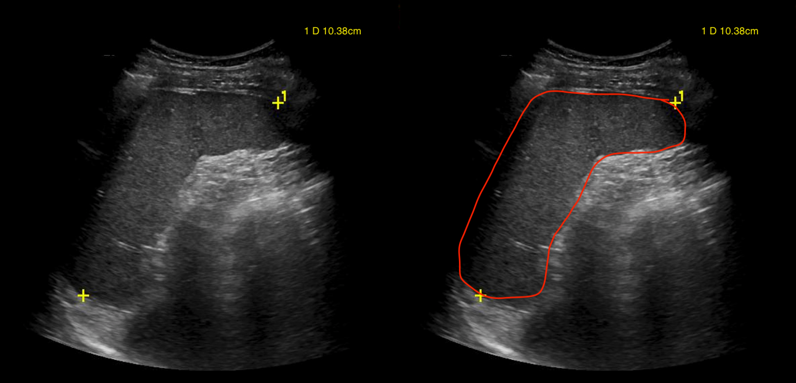
SIZE OF SPLEEN
A sagittal still image with calipers can calculate the size of the spleen (as seen in the example below).
CLIP OF SPLEEN
A clip of the spleen in this orientation should be taken (like the example below).
SPLEEN (TRANSVERSE VIEW)
The spleen can also be imaged in the transverse view. The goal here will be to take a still image in this view and a take clip showing as much of the organ as possible.
IMAGE OF SPLEEN
A transverse still image of the spleen can be taken (as seen in the example below).
CLIP OF SPLEEN
A clip of the spleen in this orientation should be taken (like the example below).
Page Updated: 02.04.2018